- Description
- Technical Parameter
- Other Instructions
- Ordering
1. Operating procedures
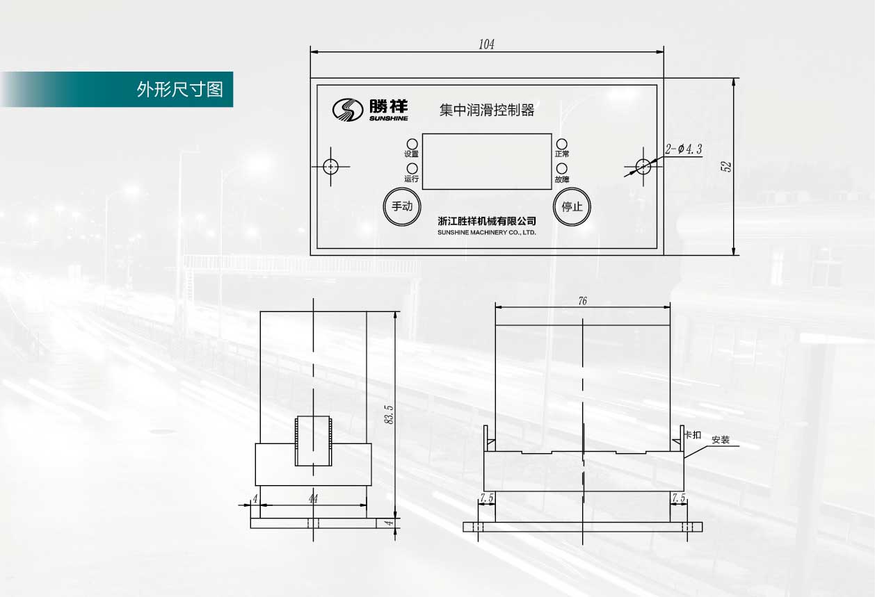
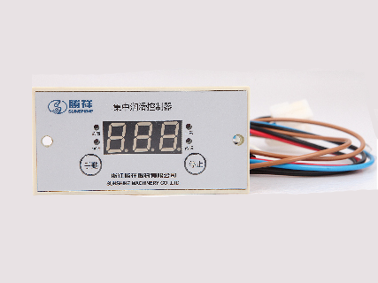
The controller acts as the brain of the automatic lubrication system, allowing the system to achieve automatic operation and set the interval time. The button of the controller has "manual" and "stop". When it needs to start, press the "manual" button for one second and the controller signals the main oil pump. When the running lamp is on, the system completes the refueling action. When there is a fault, press "stop". The button can clear the fault light and the alarm sound; if the "Stop" button is pressed during the normal operation, the oil can be stopped; when the time is set, the "Manual" button is incremented and the "Stop" button is decremented.
2. Time setting procedure
Press “Manual” and “Stop” at the same time for 3 seconds to enter the setting time state. The light is set and the digital tube displays “t1”. After 5 seconds interval, the digital tube displays “XX” as the system's pause time. Under “Manual”, the time can be increased in minutes, with a maximum of 999 points. Press the “Stop” button to make the time decrease in minutes. After the interval time is set, wait 5 seconds for the digital tube to display “t3”. After a few seconds, the digital display shows “YYY” as the working time of the system. Pressing the “Manual” button at this time will increase the time in seconds. The maximum value is 999 seconds. Press the “Stop” button to decrease the time. "t5" is the setting of the unloading monitoring time. Non-professionals cannot change the factory setting. After setting, the setting lamp goes out.
3. How to work
After the controller is turned on, the digital tube displays the countdown time, displayed in minutes (makes the system stand-by status obviously), successively decremented to indicate the system standby state, and sent the action signal to the set time to make the system run, and can also manually refuel according to actual needs at any time. The system will restart the timing after each manual completion. The system has a memory function, that is, the last time the timing did not reach a rest cycle, and it accumulates during the next vehicle travel, and it will be full one cycle.
4. Display function
(1) Energizing the controller The digital tube displays the countdown time and the time sequentially decreases, indicating that the system is in the standby state;
(2) When the system is running, the digital tube loops and the running light is on, indicating that the system is in the running state;
(3) During the operation of the system, the pressure signal is detected and the normal light is on; when there is a fault, the fault light is on and an alarm sound is emitted.
