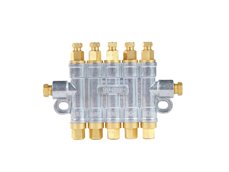
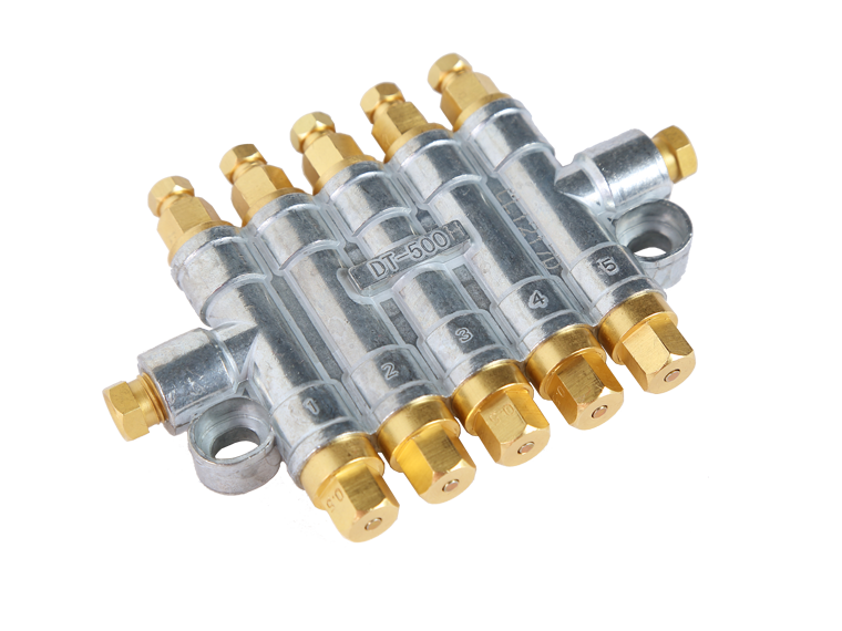
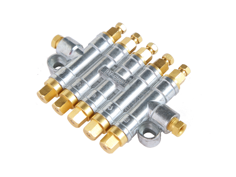
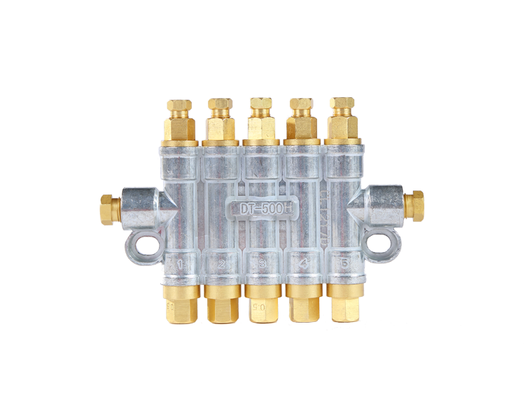
- Description
- Technical Parameter
- Other Instructions
- Ordering
Performance and characteristics:
1. Each fixed flow is supplied to the lubricating part.
2. not because of the oil viscosity and oil time affect the flow;
3. it must be used with a butter injection machine with a depressurized device.
4. It is suitable for the volume cycle lubrication system with working pressure from 15 to 30kgf/cm2.
2. not because of the oil viscosity and oil time affect the flow;
3. it must be used with a butter injection machine with a depressurized device.
4. It is suitable for the volume cycle lubrication system with working pressure from 15 to 30kgf/cm2.
Appearance size diagram

Type and technical parameters:

Type and technical parameters:
| Type | Product No. | Export number | A | B |
Spit amount of (cc/stroke) |
Weight (g) |
| DTH-200 | 20204 | 2 | 78 | 39-43 |
0.3 0.4 0.5 |
168 |
| DTH-300 | 3 | 93 | 54-58 | 232 | ||
| DTH-400 | 4 | 108 | 69-73 | 299 | ||
| DTH-500 | 5 | 123 | 84-88 | 359 | ||
| DTH-600 | 6 | 138 | 99-103 | 424 |
The working principle shows that:
 1 the lubricating oil from the medium pressure of the oil pump makes the umbrella valve in the distributor push upwards.
2 when the umbrella valve closed the core hole of the core it forced the piston to overcome the spring force to begin to rise. Remove the original lubricating oil from the upper chamber;
3. When the piston is moved to the top of the upper chamber the oil discharge is completed at the same time.
4 when the oil pump stops supplying oil the pressure relief valve opens automatically making the pressure oil in the main oil pipe back to the oil through the pressure relief valve. When the system pressure drops the piston in the distributor begins to respond under the action of the spring. When the umbrella valve returns to the distributor inlet the piston stores the lubricating oil stored in the lower cavity to the upper chamber through the core hole and the next oil supply is also ready.


