- Description
- Technical Parameter
- Other Instructions
- Ordering
Name specification

1. won the national utility model patent, patent number: 201520246835.5.
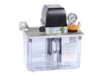
2. a liquid level switch is provided to output the abnormal signal of the liquid level.
3. a motor self protection device is provided to prevent overheating and overloading.
4. pressure relief valve can protect the pump and pipeline to reduce damage.
5. modular design, the internal non connected oil pipe convenient maintenance.
6.3L/4L model has about two exit options, convenient for customer installation.
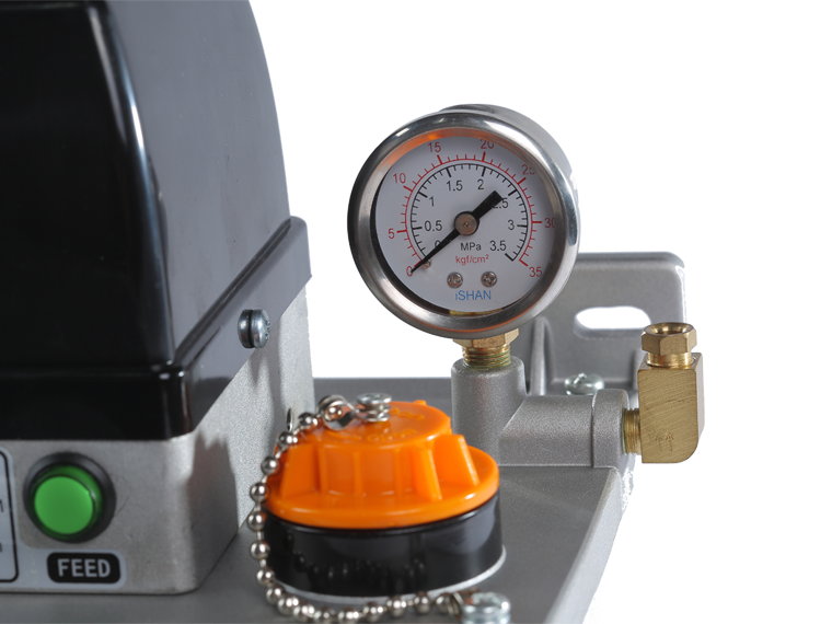
7. the pressure switch can be selected freely according to the requirements of the customer (YEK-B1P1).
8.B type machine has a "FEED" key, which can be forced to lubricate.
9. longest lubrication time less than 2min, the shortest interval is greater than or equal to 3min.
Scope of application:
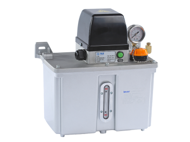
The YEK type machine is suitable for the centralized lubrication system of machine tools, plastics, textile, light industry, printing and conveyor.
Appearance size diagram

|
Single phase voltage (VAC) | Power (W) | Abnormal output connection capacity (A) | Lubrication time | Interval time | Spit out the caliber | Maximum spitting pressure (kgf/cm²) | The amount of spitting (cc/min) | Pressure switch (kgf/cm²) | Liquid level switch | Oil tank capacity (L) | Weight (kg) | |||||
| YEK-B1 |
110 Or 220 |
100 |
level switch 0.3 |
The PLC control system must be connected to the | The PLC control system must be connected to the | Ø 6 | 8 | 150 | No |
On the power of (oil conductance) |
2L(resin) 3L(resin) 4L(resin) 4L(alufer) |
2.7 | |||||
| YEK-H1 | 2.9 | ||||||||||||||||
| YEK-B1P1 |
Pressure switch 3.0 |
2.1 ↑off |
3.3 | ||||||||||||||
| YEK-H1P1 | 3.7 | ||||||||||||||||

YEK-H type wiring diagram

Hydraulic schematic diagram


